Welcome to Sharetop Technology Co.,ltd.

Hotline:+86-0755-27524036

In the tide of Internet technology, cloud computing, big data, artificial intelligence, 5G strictly adhere to the list of hot words in the scientific and technological circles, which are inseparable from the development of ultra-high-speed optical fiber transmission networks in the world, and many dedicated transmissions are applied in optical fiber transmission networks. Equipment, the important device used with these transmission equipment is the optical module.
Introduction to optical modules:
The optical module is an optoelectronic module that performs photoelectric and electro-optical conversion. The transmitting end of the optical module converts the electrical signal into an optical signal, and the receiving end restores the optical signal to an electrical signal. Its internal structure is as follows:
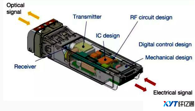
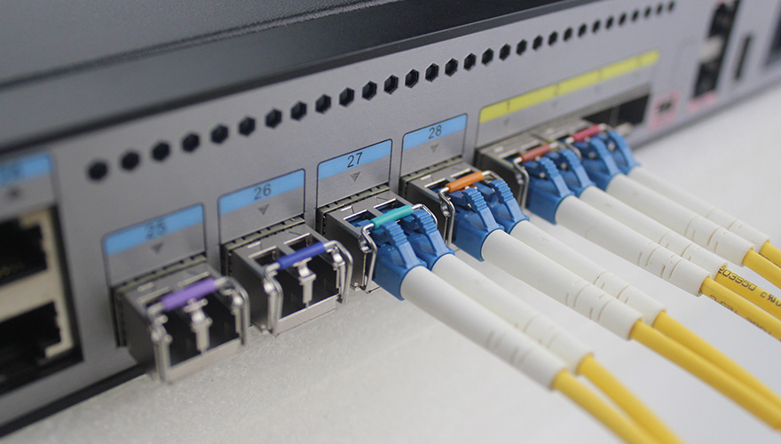
Optical module construction
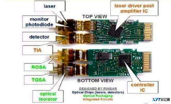
Optical module internal structure
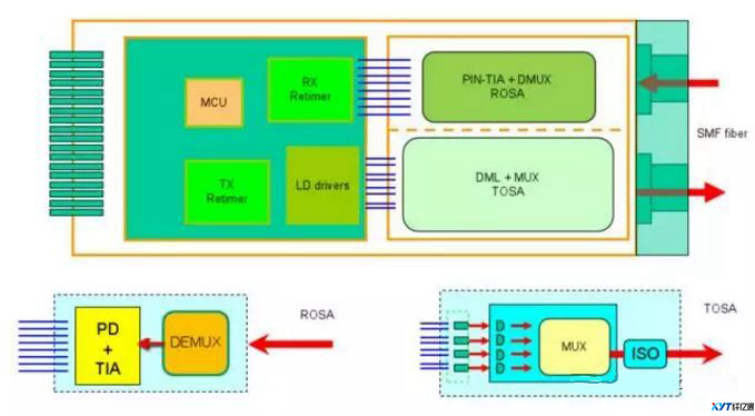
Optical module structure
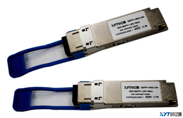
SHARETOP QSFP+ 40Gb/s
The optical module is used for transmitting optical signals, and the transmission medium is optical fibers. The optical fiber transmission method has low loss and long transmission distance, and has a strong advantage in long-distance transmission.
According to the different viewing angles, people have different understandings of optical modules:
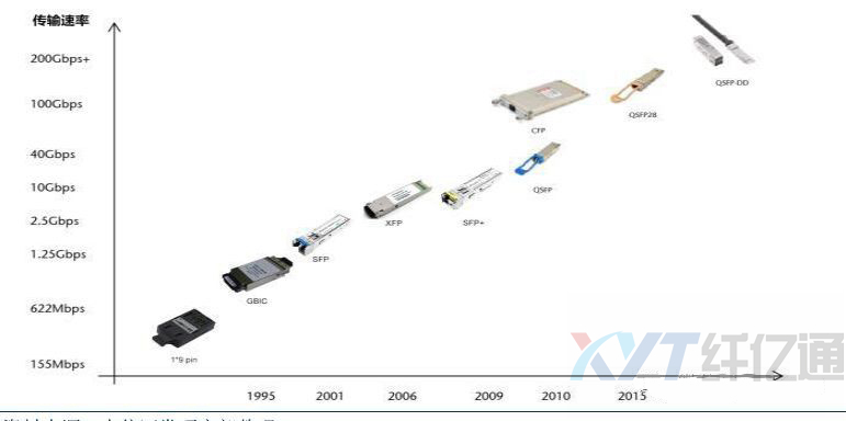
1) Optical modules divided into 1.25Gb/s, 10Gb/s, 25Gb/s, 40Gb/s, 100Gb/s, and 400Gb/s according to the transmission rate
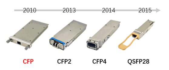
2) Optical modules classified into SFP, SFP+, QSFP28, OSFP, CFP, CFP2, CFP4, and CFP8 according to the package form
3) Divided into single-fiber and dual-fiber optical modules according to the required number of optical fibers.
4) Multi-mode optical modules and single-mode optical modules according to different access fibers
5) According to the type of transmission, it can be divided into wave splitting module and ordinary optical module.
 The optical module breaks the 100-meter limitation of the Ethernet cable in data transmission. It relies on a high-performance switch chip and a large-capacity cache to provide balanced traffic, isolation conflict, and detection while realizing non-blocking transmission switching performance. Errors and other functions ensure high security and stability during data transmission.
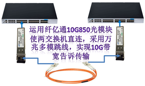
In essence, the optical module only performs data conversion between different media. The connection between two switches or routers within 0--150Km can be realized by directly connecting or adding a fiber amplifier.
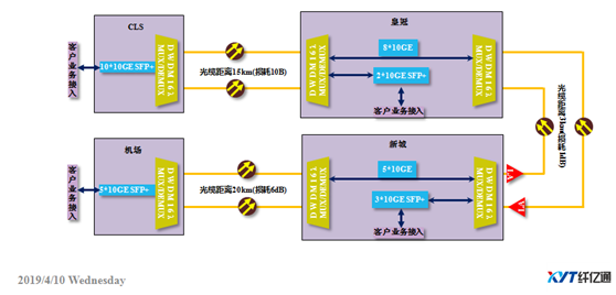
Wavelength division multiplexing transmission: When the long-distance optical cable resources are insufficient, in order to improve the utilization rate of the optical cable and reduce the cost, the wavelength division optical module and the wavelength division multiplexer can be used together to allow the multiple services to be transmitted on the same pair of optical fibers.
1) Do not touch the pins or gold fingers of the optical module.
2) The fiber must be handled with care. When taking the fiber, the two fingers need to take the physical part of the fiber connector, but not the fiber or the fiber jacket.
3) It is strictly forbidden to apply axial and lateral impact to the fiber; it is forbidden to fold or twist the fiber or compress the pigtail. Under no circumstances can the device pigtail be pulled or the pigtail coupling force be applied.
III: removal of the optical module
When removing an optical module, first pull out the buckle and slowly remove it. Do not pull the optical fiber to pull out the optical module or forcibly pull out the optical module. The optical fiber should be aligned with the optical port and flattened out. When disassembling, first pull the pull ring, the fiber is aligned with the optical port, and it is flat and flat.
IV: Precautions for the optical module not being inserted into the bottom When installing the optical module, force the module to the end and hear the sound of the beat or feel a slight vibration, indicating that the module card is stuck in place. When the optical module card lock is not in place, the finger and the connector on the board are in micro contact, and the link may be connected. However, in the case of vibration, collision, etc., the optical module may be short-circuited or even loose. When inserting, make sure that the handle ring is closed (the card lock is used for positioning); after inserting, pull out the optical module to check whether it is installed in place. If it is not pulled out, it means that it is inserted.
V: Use of optical modules
When using a jumper to connect the optical module, the module should not receive light above the module's light-receiving range. Otherwise, the module will be damaged if it is too high (requires an optical attenuator to connect), and the module will not work properly.
VI: Precautions for optical port contamination of optical modules.
1) The site must be equipped with rubbing paper. Before the jumper is inserted into the optical port, it must be cleaned first to avoid cross-contamination of the optical port due to contamination of the end face of the optical jumper, which is difficult to clean.
2) The optical module that is not in use must be equipped with a dust cap to avoid dust pollution. If there is no dust cap, the fiber can be used instead, and dust can be effectively prevented.
3) The fiber optic patch cord that is not in use must be installed with a dust cap to avoid dust pollution. Then it is neatly hung on the fiber optic rack or inserted into the fiber optic package, and the fiber cannot be squeezed.
4) If the optical module or fiber is not used for a long time without a dust cap, it must be cleaned for the optical port or fiber when it is used again. The optical port cleaning is performed using a cotton swab, and the fiber port cleaning is performed using a rubbed paper.
5) If the signal is abnormally lost during the operation of the device, you can use the above cleaning method to clean the optical port and optical fiber of the optical module to eliminate the pollution factor.